AVR Analog Comparator
Introduction
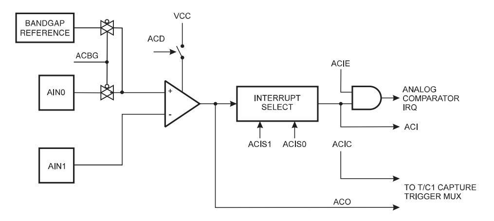
AVR Analog comparator can be used to compare two analog inputs. The Analog Comparator compares the input values on the positive pin AIN0 and negative pin AIN1. When the voltage on the positive pin AIN0 is higher than the voltage on the negative pin AIN1, the Analog Comparator Output, ACO is set. the comparator can trigger a separate interrupt, exclusive to the Analog Comparator. We can select Interrupt triggering on comparator output rise, fall or toggle. Following is a block diagram of comparator and it's logic.
Registers
ACSR (Analog Comparator Control and Status Register) is an 8-bit register which contains configuration bits for Analog Comparator.
-
ACIS0, ACIS1 (Analog Comparator Interrupt Mode Select) - These two bits determine which comparator events
that trigger the Analog Comparator Interrupts. The different settings are shown in the table.
ACIS1 ACIS0 Interrupt Mode 0 0 Comparator Interrupt on output toggle 0 1 Reserved 1 0 Comparator Interrupt on Falling Output Edge 1 1 Comparator Interrupt on Rising Output Edge
- ACIC (Analog Comparator Input Capture Enable) - When written logic one, this bit enables the Input Capture function in Timer/Counter1 to be triggered by the Analog Comparator.
- ACIE (Analog Comparator Interrupt Enable) - Setting this bit one activates Analog Comparator Interrupts. Setting this zero disables the interrupts.
- ACI (Anaglog Comparator Interrupt Flag) - This bit is set by hardware when a comparator output event triggers the interruot mode defined by ACIS1 and ACIS0.
- ACO (Analog Comparator Output) - The output of the comparator is directly connected to the ACO.
- ACBG (Analog Comparator Bandgap Select) - When this bit is set, a fixed bandgap reference voltage replaces the positive input to the Analog Comparator. When this bit is cleared, AIN) is applied to the positive input of the Analog Comparator.
- ACD (Analog Comparator Disable) - When this bit is set, the power to the Analog Comparator is switched off.
Sample Code
In the following example, an analog comparator is used to light up a LED, when temperature sensor is reached to certain temperature limit.
Use Analog Comparator without Interrupts
Use of Analog Comparator without Interrupts is very straight forward. We use while loop to scan whether ACO is set or not and update LED indicator according to its value.
#include <avr/io.h>

int main()
{
    unsigned char temp;
    DDRD = 0x01;                // Set PD0 as output
    ACSR = 0x00;                 // Configured the Analog Comparator

    while(1)
    {
        temp = ACSR;            // Get the values from ACSR
        temp ∓= 0x20;            // Isolate the ACO bit

        if(temp & 0x20)            // Test if ACO is set
            PORTD &= ~0x01;        // Turn LED OFF  - if ACO = 1
        else
            PORTD |= 0x01;        // Turn LED ON - if ACO = 0
    }

    return 0;
}
Use Analog Comparator with interrupts
To enable intterupts for Analog Comparator, you have to do following steps.
- Enable global interrupts
- Enable Analog Comparator interrupts
- Implement ISR for ANA_COMP vector
#include <avr/io.h>
#include <avr/interrupt.h>

ISR(ANA_COMP_vect){
    int state = ACO;
    switchLED(state);
}

void switchLED(int state){
    if (state)
        PORTD = 0x01;
    else
        PORTD = 0x00;
}

int main(void)
{
    sei();                        // Enable global interrupts
    DDRD = 0x01;                // Set PD0 as output
    ACSR = 1 << ACIE;             // Configure Analog Comparator
                                // Enable Analog Comparator interrupts
                                // Trigger when toggle, both ACIS1, and ACIS0 are set to 0

    while (1)
    {
    }
}


Comments
Post a Comment