Posts

Showing posts from May, 2018

Bluetooth Module Interfacing with AVR

Image
Hi everyone! Today we're going to learn how to interface Bluetooth module with AVR microcontroller and how LED is controlled remotely using smartphone. In this lesson we're going to develop our own mobile application using Android Studio to communicate with the Bluetooth module. If you're not familiar with USART serial communication , please read it before going through this lesson. Interface Bluetooth Module Bluetooth module can be interfaced either by using Interrupts or without Interrupts. I recommand to use Interrupts because, we don't need to always search for UDR (USART Data Register) for received data. Here I'll show you how microcontroller is programmed in both ways. Circuit diagram First, add bluetooth library to your project and include bluetooth.h header file. Without Interrupts #include <avr/io.h> #include "

AVR Sample Codes

Image
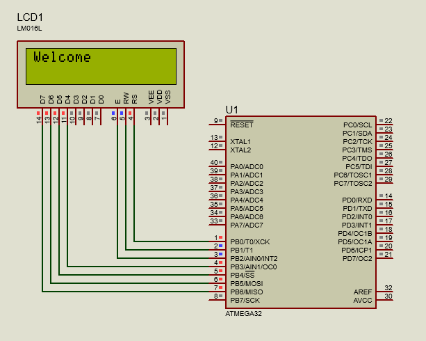
Interface LCD with AVR Circuit diagram #include <avr/io.h> #include "lcd.h" int main(void) { lcd_init(LCD_DISP_ON); lcd_puts("Welcome"); } Download Library Interface Keypad with AVR Circuit diagram #include <avr/io.h> #include "lcd.h" #include "keypad.h" int main(void) { lcd_init(LCD_DISP_ON); keypad_init(); char key; while (1) { key = scan_for_key(); if (key != 0xFF) { lcd_putc(key); } } } Download Library Interf

AVR Interrupts

Image
What are Interrupts Interrupts are basically events that require immediate attention by the microcontroller. When an interrupt event occurs the microcontroller pause its current task and attend to the interrupt by executing an Interrupt Service Routine (ISR) at the end of the ISR, the microcontroller returns to the task it had pause and continue its normal operations. In order to enable interrupts for a particular event, you have to complete following steps. Enable global interrupts. Enable Interrupt Enable bit of specific Interrupt. Implement ISR (Interrupt Service Routine) for specific Interrupt. Interrupt request Following is a list of interrupt vectors available in Atmega32A microcontroller. Vector No. Program Address Source

The USART of the AVR

Image
Super-simplified UART interface USART stands for Universal Synchronous Asynchronous Receiver/Transmitter. UART stands for Universal Asynchronous Receiver Transmitter. They are just a piece of hardware that converts parallel data into serial data. The difference between USART and UART are that UART supports only asynchronous mode, whereas USART supports both asynchronous and synchronous modes. In asynchronous transmission, start and stop bits are used to identify data bits, while in synchronous transmission, bits are synchronized with a clock pulse. Some of the features of AVR USART is given below. Full Duplex Operation (Independent Serial Receive and Transmit Registers) Asynchronous or Synchronous Operation Master or Slave Clocked Synchronous Operation High Resolution Baud Rate Generator Supports Serial Frames with 5, 6, 7, 8, or 9 data bits and

AVR Analog to Digital Conversion

Image
Most of the real world data is analog. There are sensors to measure light intensity, temperature, pressure, voltage etc. But these sensors give their output relative to voltage scale. When programming the MCU, we have to do some calculation on their output to get the actual value. The MCU component that is very helpful in this process is called ADC (Analog to Digital Converter). The conversion process happens in 3 steps. Sensor senses the real world physical parameter and convert it to eqivalent analog electrical signal. Analog signal is converted to digital signal using a Analog to Digital Converter (ADC). This digital value is then fed into the CPU and processed accordingly. Almost all MCUs have ADC. In Atmega32A, PORTA contains the ADC pins. These 8 ADC pins are multiplexed together. Some of the features of ADC are given below. 10-bit Resolution 0.5 LSB Integral Non-Linearity

AVR Analog Comparator

Image
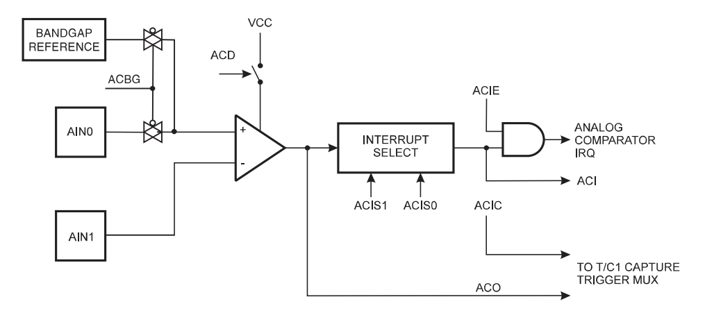
Introduction AVR Analog comparator can be used to compare two analog inputs. The Analog Comparator compares the input values on the positive pin AIN0 and negative pin AIN1. When the voltage on the positive pin AIN0 is higher than the voltage on the negative pin AIN1, the Analog Comparator Output, ACO is set. the comparator can trigger a separate interrupt, exclusive to the Analog Comparator. We can select Interrupt triggering on comparator output rise, fall or toggle. Following is a block diagram of comparator and it's logic. Analog Comparator block diagram Registers ACSR (Analog Comparator Control and Status Register) is an 8-bit register which contains configuration bits for Analog Comparator. ACSR (Analog Comparator Control and Status Register) ACIS0, ACIS1 (Analog Comparator Inter

Basics of Microcontrollers

Image
Hi everyone! Today we are going to talk about basics of microcontrollers. This guide is for those who want to learn AVR programming quickly. This guide only gives basic information about AVR programming. Those who want to learn more deep can use following websites. http://www.avr-tutorials.com https://www.sparkfun.com https://www.avrfreaks.net http://maxembedded.com Ok. Enough intro. Let's get started with our lesson. Basic Components Atmega32A Microcontroller Basically, a microcontroller is a small computer on a chip which can perform input, output, storing, processing, interrupts etc. Microcontrollers atleast have following basic components. Block Diagram of the AVR MCU Architecture

Operating Systems - Introduction

Image
Introduction Operating system placement An operating system (OS) is a software that manages hardware and software resources and provide common services for computer programs. Operating systems performs all the basic tasks of the computer like process management, memory management, file management, handling input and output and controlling peripheral devices such as disk drives and printers. Before go into further details, let's look into history of operating systems. History The First Generation (1945–55) Vacuum Tubes and Plugboards The electronic computers first introduced in 1940s were run without any operating systems. They were designed, built, programmed, operated and maintained by a single group of people. They were programmed in absolute machine language, the basic functions of the machine were controlled usin

Popular posts from this blog

Flutter - Create Image Container with Round Corners and Splash Effect

AVR Analog Comparator

JAudioTagger - ID3 tagger library